Micro Projects Home Page

Home

 Microprocessor Basics

Micro Basics

Site Projects

Site Projects

Construction Techniques

Construction

Programming concepts

Software

Projects

Projects

8085 page

8085 page

 Project 1 Page 5

I, like most home constructors would like to think that my projects are destined to work first time without error, but most of us will make a mistake from time to time, quite often because of a misunderstanding with the information obtained from a data sheet.

As I�ve already admitted, I made a number of errors in the site�s constructional project, none of which took a great deal of time to locate, but could have been nigh impossible without some basic knowledge and a few items of test gear. Let us therefore take a brief  look at this site�s project with an oscilloscope,  mentioning the LOGIC PROBE, which is an easily affordable tool that can make the difference between pin-pointing the fault, and �throwing in the towel.� All of the following traces were recorded with the program in the initial �Time Setup� mode just after reset:

Picture

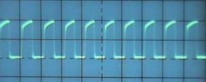
This is quite simply the system clock on MY example with it�s 1MHz ceramic resonator. Note that ALL traces in this series are 2V / Cm in the vertical plane. In this case the TIMEBASE is set to 1uS/cm, meaning that each cycle you can see takes place in exactly 1uSec - i.e. 1,000,000Hz.

A good logic probe will show if a �clock� signal IS present , but will not tell you if it has inadvertently �doubled� itself (as can happen sometimes to an oscillator- even a crystal one).

Picture

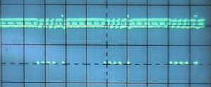
And to the one on the right? Pretty isn�t it? No, it hasn�t gone wrong; this is actually the I/O request signal from the CPU pin 20. Seen with a timebase of 50uS/S, the I/O appears to be active in groups of four, with a fifth tagging on a bit behind. Guessed yet? The first four are updating the display and the fifth is reading in the keypad word.

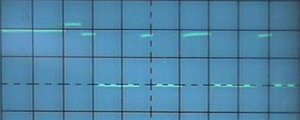
A bit more difficult to see, but still at 1uS/cm, we can see the Memory Request signal from the Z80 CPU on pin 19. Remember that this signal is a NEGATIVE signal, which means that when it is HIGH (like at the beginning of the trace at the LH side, the processor is probably in an I/O cycle.

Picture
Fault Finding

Fault Finding

Data Sheets

Using a good logic probe here will probably reveal far more interesting information than that obtained in the system clock detection earlier on. It is often very important to see IF the CPU is trying to access an I/O device (or whether it is not) during a certain phase of a program. The logic probe tells us this without having to look for a small and maybe obscure pulse on a scope trace. Also bear in mind that the Clock program is �polling� for it�s information, which gives us an easily spotted repetative waveform to look for.

Data Sheets

EEprom Programmer

Programmer

Video Information

VIDEO info

Peripheral Circuitry

Peripheral circuitry

Central Heating and Z280's

Z280 and  Central Heating  Controllers

Picture

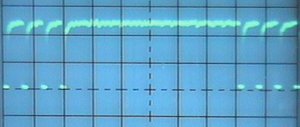
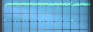
No guesses for this one! A solitary infrequent negative going pulse? This is a give away isn�t it? Yes, it�s the missing I/O pulse from the waveform above; namely the KEYPAD read pulse on the output of IC7 pin 6. A combination of OR-ing READ and I/O REQUEST.

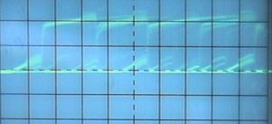
I agree! Compared to the  display above, this one is a MESS! Nothing obviously repetative here, and we happen to be looking at A0 on the ADDRESS BUS. More useful than at first glance as it may well  reveal an in-between �bad� level between the + (at roughly +4Volts in this trace) and ground. The little triangular bits are where the bus is momentarily disconnected from the drivers and is trying to �float�.

Any guesses where this is on the circuit? Four repetative negative pulses? Display refresh? Correct, but where? No keypad I/O? There�s only one place where we can see the display refresh ONLY, and that�s at the output of  IC7 on pin 3, where we�re OR-ing the WRITE and I/O REQUEST signals.

Picture
Picture
Concluding Ideas

Concluding ideas

And the logic probe? No scope to hand and no processing from the circuit? Check it out with the probe and note the results. A signal such as this should reveal a healthy clocking indication, a permanent LOW or HIGH, or a signal with infrequent transitions suggests an address line fault. Which might be what? In a new device it could be a disconnected wire, solder splash or incorrect connection. In a once WORKING piece of gear, it would suggest a processor fault or a peripheral chip fault (one which is connected to the address bus). It is highly unlikely that a program type error would cause this.

Links

Links

http://www.hampshire-shops.co.uk

PAGE 6

PAGE 4