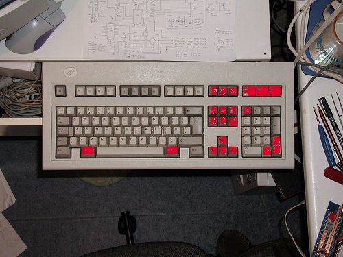
Micro Projects Home Page

Home

 Microprocessor Basics

Micro Basics

Site Projects

Site Projects

Construction Techniques

Construction

Programming concepts

Software

Projects

Projects

8085 page

8085 page

Fault Finding

Fault Finding

Data Sheets

Data Sheets

EEprom Programmer

Programmer

Video Information

VIDEO info

Peripheral Circuitry

Peripheral circuitry

Central Heating and Z280's

Z280 and  Central Heating  Controllers

Concluding Ideas

Concluding ideas

Links

Links

 6809 Project

It�s here at long last! A new site project for 2002, namely a PC AT KEYBOARD INTERFACE. Whilst I could be rejoicing that it is now done and dusted, I did NOT enjoy designing it as it was a real PAIN to make work - let alone complete. OK so enough of my complaining, lets talk about the details of the project.

SPECIFICATION:  Whilst it would have been nice to build around a smart commercially made model with decent key-switches, but no decoder, I decided in the end that as PC AT keyboards were 2-a-penny and even very cheap when purchased brand new, there was simply no excuse for not basing the site project around one.

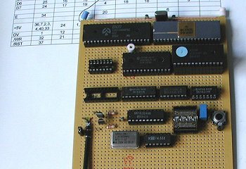
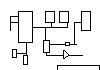
DESIGN SPEC:

Micro based (of course); being pressurised my the Motorola fan club :) I used the MC6809 for the processing power. The choice of output interface was split about 50-50 over a serial connection or  a parallel connection to feed directly into a project. In the end I decided to go for both in the one design, selectable by a jumper link on the board. Obviously the components for the unwanted interface can be omitted. Hardware has been kept to a minimum (as usual), the minimum ROM requirements being 2K (although to use anything smaller than the 2764 I used, a lot of the code would have to be relocated) with 256 bytes of RAM. I suspect though, that most will opt for a 2Kx8  6116 or equivalent. In order to cover the whole range of available RAM devices, the stack has deliberately been kept to a low address. Two crystals are required, a 4MHz one for the 6809, and a 2.4576MHz for the serial comms - if this is to be used. In common with a lot of my projects I have chosen the Zilog 8530 SCC serial interface LSI, which works very well with the 6809.

First PC AT Keyboard interface

To the left we see a picture of the first working prototype. The display was (fortunately) installed for diagnostic purposes. It shows transfer status (serial or parallel) whether a shift or control key is being pressed in addition to another key, the decoded character (if displayable) and the number of bytes received for that particular key combination. A PC AT keyboard sends anything between one and eight bytes of key-code to signify any ONE key condition. Not only are there combinations for all keys on the keyboard, but also another full set showing when a key has been released!

For reasons best known to IBM, the keycodes bear no resemblance to the character they signify. Equally, the codes are in no particular order :  A, B and C are in fact :  1Ch, 32h and 21h as an example. Key release codes are generally 2 or 3 bytes long and are created by adding F0h or E0h F0h in front of the original key make code. Confusing? I�ll say! There are in fact THREE code sets in all and all are different. I simply went for the universal one that 99.9% of keyboards default to on power up.

PROTOCOL

What protocol?? :) Well the interface is of the standard PS2 type, regardless of whether the keyboard has a big 5 pin DIN or the smaller MINI-DIN connector. That�s why you can connect either to either with an adapter. No, seriously, the protocol is a type of  bi-directional synchronous affair who�s transmission speed can be anywhere between roughly 12K and 30K. (depending on the keyboard)  In order for anything to read the information being sent, the �receiving device� has to synchronise itself with the clock being sent from the �sending device�. It can respond and send the keyboard commands by overriding the sent signal if need be.

IMHO the PC AT keyboard may be very flexible, but is grossly over-complicated for the processor overhead needed to read it!!  Interestingly enough, my first effort to talk to one of the things was a complete disaster as my processor (the 6809) was too slow when using my modest software.(development software that wasn�t particularly well written or optimised) As I was using an 68B09 (the double speed 6809) I proved this by doubling the clock speed to 8MHz- and suddenly the thing burst into life! OK a fix for me but not a fix for all sorts of 6809, so I trashed that code and optimised it from square one until it would run on a standard 6809 -which it does - fortunately with time in hand.

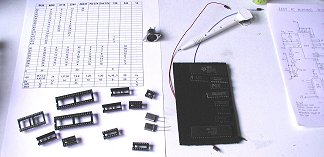
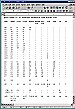
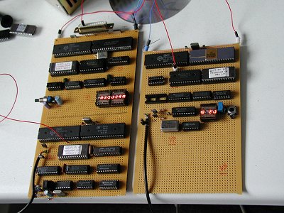
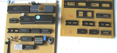
As there were so many alteration and changes to the layout, circuit, components etc. etc. during development and to ensure that YOU have a working circuit to replicate, I ended up building a SECOND prototype! To the right you see the second set of components and the wiring list to be tried out.

Parts
Underside of PCB for version 2

To the left you can see the standard method of construction I use with the wiring combs fitted to the back of the board around the IC sockets. If a parallel only version is to be constructed, then it should be possible to construct one with 1x40pin package - the 6809, 1x28 pin package - the 2764,  a 24 pin package for the RAM (on this occasion I used a TMS2018 2Kx8 which is pin compatible with the 6116 and only half the width) 3x 20 pin packages, a 244 and a 374 to interface with the keyboard and a 374 for the parallel output connection. Lastly, you�ll need the services of a 74LS138 decoder and a 74HC14 hex inverter. That�s a 16 pin and a 14 pin. One of each. (The 74LS32 is only needed for serial)

The image below shows the original prototype next to the sockets laid out for the second. Note that in the second assembly, I installed BOTH interface options, so there are more sockets than in a single output option build.

Made and unmade versions

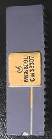
Semiconductors Used in the Second  Prototype

MC6809L

CPU

I tried an EF68B09 as well to check that there were no problems with the faster chip.

8530 SCC

Serial ctlr

Standard Zilog Z053006PSC dual serial interface controller. I could have used a 6850, which would have been easier with the software but I didn�t have one to hand.

2764

EPROM

With the program under 2K bytes it would thoeretically fit into either a 2716 or 2732 - but many of the addresses & pointers would need to be re-located in order to do this.

TMM2018

RAM

The program needs a RAM window of less than 256 bytes, thus any amount of RAM above and including this size may be used. This device is simply an ultra-fast �skinny� version of the ordinary 2Kx8 6116. The first prototype used an HM6264 8Kx8

74LS374

Keyboard interface 1

This octal latch is used to transmit data TO the keyboard

74LS244

Keyboard interface2

This octal buffers receives data FROM the keyboard. It also has a line connected to a link on the board to determin whether serial or parallel interfacing is required.

74HC14

HEX Schmitt inverters

Used for the serial clock, the reset line and others. PLEASE NOTE. I tried using the standard LS version in place of the HC but the waveform was not accepted by the SCC chip and the system hung! Beware - I�ve been there and done that already!

74LS32

Quad OR

Used ONLY with the serial application, so for parallel only can be omitted.

74LS138

Decoder

Used for both memory and I/O decoding

VN10KM

FET

Used to drive the PS2 clock and data lines. If using a bipolar device, remember to incorporate base resistors. I was unsure as to how much load the transistors were going to need to switch at first so these are overkill...but I had some to hand.   :)

OTHER COMPONENTS REQUIRED:

Reset push switch, decoupling capacitors, 10u 16V capacitor (for the reset) 1N4148 diode, 4Mhz crystal (for the 6809) 2.4576Mhz crystal (for the serial comms - optional) 2K2 resistors, 150pF capacitor, 22pF capacitors, 1K5 resistors,

MAKING IT WORK!

Unlike most other projects I have described on this site, there are no displays or LEDs to tell you whether all systems are go or something is amis; clearly a little help in this area will aid the recifying of any problems.

To check and see if the projects is working, I will assume that the builder has access to two items of test gear, namely:

*** A multimeter.

*** A decent working logic probe.

A scope would be nice but is not really necessary to determin whether the processor is running at this stage.

1) Check that the wiring is correct and complete, then do a resistance check with the meter on the basic power rails for no shorts between +5V and 0V and continuity to the appropriate power pins on the IC�s. Plug in the 74HC14 and then apply power to check the operation of the reset line going to pin37 of the 6809. If all seems OK, remove the power and plug in the rest of the IC�s.

2) With a meter set on AMPS, connect in series with the power and quickly ascertain that the total power is below 450mA (say, 1/2 Amp max.). If it is a lot greater than this, turn off and remove each IC in turn to ascertain why.

The power up sequence after a hard reset will signify whether the micro is running or not. If it IS running, then if things don�t materialiase from the keyboard, at least you will have a good idea where to look and what not to blame. If you follow the table below, the sequence of events should become clear:

3) As the LS138 Decoder chip is the centre for all I/O and MEMORY access, note the activity on all it�s following pins immediately after a hard reset. You�ll need the logic probe attached to each pin in turn before pressing reset. NO KEYBOARD IS ATTACHED FOR THESE TESTS

6809 - date code 1983

7

/ROMEN   Clocking activity all the time.

9

/RAMEN   RAM access. Clocking activity for almost one second then level should stay high

10

Not used. Originally an LCD display enable. NO activity should ever be seen. Always high.

11

/SIOEN     Clock burst after reset then high. This is regardless of position of jumper link.

12

/DISPEN   Diagnostic display enable. (not fitted) Two short bursts then signal stays high.

13

/244ENABLE   Keyboard  read device. Delay of about 1/2 sec then continuously clocks 

14

KEYBOARD WRITE DEVICE   Single clock pulse after reset then a continuous high level

15

/PAREN  Data output strobe. No activity. Continuous high level.

Thus when sitting idle after reset, the only decoded activity should be on 138 pins 13 and 7.

A few ideas to aid troubleshooting.

Pin 15 /PAREN will ONLY ever toggle low when the 6809 thinks it has decoded and matched a word (i.e. a valid character). The parallel will always clock regardless of the link position on the board.

If on receipt of a character from the keyboard, all activity stops dead (particularly  pin 13,  /244ENABLE) the comms chip could be causing this; i.e the 2.4576 clock is noisy. To prove this one, remove the jumper link to enable parallel only, reset the system and check for the same activity, but this time without the serial chip supported in the program.

Remember that the serial output from the 8530 is at TTL level. To drive RS232 or any other variant, you�ll need to add an interface chip like a MAX232. The PARALLEL output is latched onto the output pins of the 374 after a strobe on the 374 pin 11. The strobe should be sent to the host system to tell it that a new character has arrived. It may be necessary to invert or even stretch the width of the pulse with a one-shot.

Program listing
schematic

Click on the icon to download the full 6809 program listing.

Click on this icon for the full schematic. It is about 170K in size so please be patient!

Click on this icon to download the 6809 core wiring list.

Core wiring list

6809 meets 8085! As you can see in the picture on the left, I built the second 6809 interface circuit on the bottom of the 8085 site project board. The first 6809 keyboard interface is of course to the right. Here I was just checking out the codes being sent by the 6809, against the display on the 8085 site project. How useful! If you�ve already looked at this project, you�ll recall that it displays the HEX of a character being sent down a serial line; in this case both are at 2400 baud so are immediately compatible. What I�ve done here is taken the serial output from 6809 project (1), and fed it into the serial input (the 25 way D type) of the 8085 board. There is a PC keyboard attached to 6809 interface (1); i.e. the lead disappearing in the middle of the screen. The diagnostic display on the 6809 board is reading: S  2J which tells us that the serial link is enabled, the last character to pass through was 2 bytes long (the key-up for the J) and the J shows that the last character was in fact a J. The 8085 display reads: RX>J=4A which confirms that the character sent was indeed an upper case J.

First build with 8085 interrogation...

KEYS SUPPORTED BY THE INTERFACE

With a program that is essentially a gigantic look-up table, I could see no point in writing lots of unnecessary extra code to support keys that were PC specific and would therefore probably never be used. Thus there are a number of keys that send NO code when pressed. Hopefully, I have included most / all that anyone needs to use with their project. Of course, if it does not, then there is no reason why they should not add them to the program themselves.Notice that although the Function keys are PC specific, I�ve allocated them ASCII values to allow them to be used. As a summary of the keys supported, please refer to the following table:

A-Z uppercase inc. !�$%^&<>:@ etc

 ALL KEYS

a-z lower case inc. \,./;�#[]-=` etc. & Esc

ALL KEYS

Numbers 1-0 & Keypad 1-0 plus /*-+

ALL KEYS

Cursor keys, Insert, delete, home,  blank

NONE

Print screen pause and all Locks

NONE

Holding down either shift key gives upper case of appropriate keys. Holding down either control key gives the full range of correct control characters from their associated keys.Tab inserts a horizontal tabulation code.

Alt, Alt Gr, Caps lock, Keypad Del, Enter & any Status LEDs not supported.

To make this easier to understand, see the image below of a typical keyboard with the UNsupported keys shown in RED.

It goes without saying that I want to see you guys and gals building this project as it�s nearly driven me round the bend at times over the last 3 months. If you have any questions, queries etc. please email me!

As a passing thought, for the more curious project builder, I would thoroughly recommend adding the diagnostic DL1414 display to the board - if only to play with it and understand the interface better. It can always be removed for another project. All it will cost is a DIL socket as the software is already built in.


Keyboard showing unsupported keys

http://www.hampshire-shops.co.uk