Micro Projects Home Page

Home

 Microprocessor Basics

Micro Basics

Site Projects

Site Projects

Construction Techniques

Construction

Programming concepts

Software

Projects

Projects

8085 page

8085 page

Fault Finding

Fault Finding

Data Sheets

Data Sheets

EEprom Programmer

Programmer

Video Information

VIDEO info

Peripheral Circuitry

Peripheral circuitry

Central Heating and Z280's

Z280 and  Central Heating  Controllers

Concluding Ideas

Concluding ideas

Links

Links

 Z280 Central Heating Controller

This page will probably be of most interest to someone either wishing to use a Z280, or intent on designing their own heating controller. There seemed little point in including all the details as the unit was designed to work with my own heating system and would therefore not work properly with another one, Sorry!

Z280

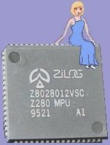
Sadly the Z280 had a relatively short life in production, but one that was meant to help bridge the gap between the Z80 and faster and more complex devices. It was a toss-up in the end which processor I was going to use for this project so the size limitations and the features I needed eventually settled things. For my project I was going to need a UART and, to make life easier in some areas, a counter / timer. Z280 has both of these built in, plus many other facilities I would not be using on this occasion.

Z280 undersocket view
Z280 Central Heating Core Wiring

Z280 undersocket

Z280 C.Heating Ctlr. Core wiring list

Designing the system

Tea mug empty? Time for another break!

Complete Z280 system board

Perhaps the most off-putting thing about the Z280 is the chip packaging. Lots of pins in a rather small space! In the end I drew a simple diagram of the chip socket underside to help me make zero errors on this bit. Click on the link above to see the full sized pin-location chart. I have also included the Z280 core wiring list to help anyone who might like to compare notes with �what pin did I  use for what?�

Z280 running for the first time

Voila! It�s awake! Clearly I didn�t make too many wiring errors underneath that socket then.  Note the absolute minimum chip-count to have something on the display. Z280, ROM, 74LS139 decoder, 74LS374 and a 74F32. The Z280 has a built-in oscillator for a crystal from 20-40MHz  I actually used 2.4576Mhz - to divide and use for the baud rate clock. It is useful that one of the internal counter / timers can take it�s input from the system clock.

Completed system board, now incorporating RTC chip with battery, ADC0809 A-D converter for analog temperature inputs and 8255 for I/O stuff like boiler / pump / valves and push switches. I�ve used a display for test purposes, but I must cut a hole in the lid of the box as you can�t see it at the moment! I found the display was absolutely essential for debugging. Note the cream TLP504 dual opto package for isolating the motor valve switch inputs. (telling the processor when the motor valves are open) I used more opto couplers in the interface box with the relays in it. Also on the board is an LM358 dual op-amp, a 555 timer as a watchdog and a MAX232 (on the upright piggy-back board at the very bottom) as I ran out of room!

Physics temperature experiments

What fun! Takes me back to days in the physics lab at school - the things we do in the interests of  science! I was doing some temperature measurements with a REF02 temperature sensor into the A-D converter.

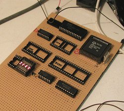
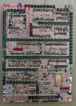
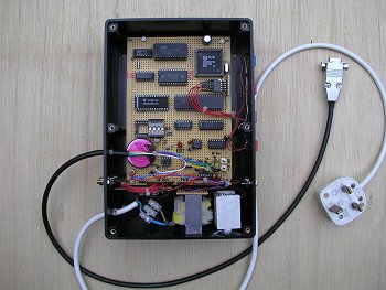
The underside of the finished board showing how I ran out of room - so much so that I had to put the MAX232 RS232 converter chip out on a piggy-back board on the top! The red square doesn�t even start to show how tight things are when wiring up the 68 way socket for the Z280. I  found it strange that even with all those pins the thing still had a multiplexed Address and Data bus! For those observant enough to spot the bit of vero-board stuck near the bottom right hand corner, this was covering the RTC lithium battery pins to ensure that nothing shorted them whilst the board was in it�s development stage.

Once the design had been checked and was working fine, I substituted HC chips where I could  and the complete circuit (including DL1414 display) now uses a fraction over 100mA which I thought was quite acceptable.

Two more noteable points were:

a) The �Watchdog�. In the interests of keeping the controller on-track, regardless of power cuts and glitches, I built a Watchdog reset circuit using a 555 timer with a 1 second cycle. For those not familiar with the concept, a circuit such as this has a 555 connected directly to the RESET line of the processor.  If the processor crashes for any reason, the 555 completes it�s cycle and the RESET line is toggled.

Back of the Z280 system board

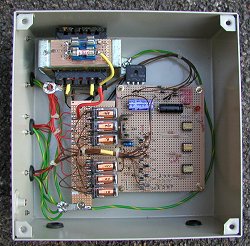
In order to stop the processor being reset every second, the program has to incorporate regular �refreshes� that access the timer (in my case via a line from the 8255) which shorts the timing cap to ground and thus delays the �reset� happening for another second. (ad-infinitum)

b) I used some of the non-volatile RAM in the RTC chip to store the status information on which relays are in operation at any time, thus creating a �recovery� situation in the event of a complete power failure. Quite impressive to watch when working properly (I know - as it should!) one can pull the power plug from the wall, hear all the relays drop out, then shove it back in again a few seconds later and everything carries on as it did before the interruption.

Inside the relay interface

The image to the right shows the setup partly completed with the interface box screwed to the wall but the main Z280 board still moveable in it�s box on the floor. All connections between the two boxes are via a 25 way �D� connector. The other lead snaking it�s way out of the boiler cupboard and around the

And the interface? Connected via opto-isolators as I mentioned before; experience with another system I built some years back gave spike problems from the relays - hence the large metal box, separate power supply and isolation. Nothing more than a collection of relays, MOSFET drivers and opto-isolators. There are LEDs on the front panel to show which relay is operating - extremely important for debugging purposes and useful when the thing is up and running. The 6 relays control the two circulation pumps, the two motor valves, the boiler �enable� line and the immersion heater (via a 30A relay in the loft) - the small 8A in the box simply switches the power to the main 30A one.

Testing the system

corner is the serial comms lead to the laptop on my table! Eh? Why serial comms? (I hear you say). Well the idea developed from the beginning to avoid the customary plethora of buttons and displays needed to set the time and the timer values, plus some way of checking the room and water cylinder temperatures etc. etc. In the end the serial link turned out very useful for checking such things, thus allowing me to sit down comfortably and operate the controls remotely! For anyone else who might be contemplating building a system of their own, they might like to make it possible to change the timer on-off times etc. from the control box, but as I NEVER changed my settings on the old box, I simply transferred these values to the Z280 and programmed them directly into the EPROM. As I said, this is MY choice and others may like more flexibility. Also programmed into the EPROM is the hot water temperature setting and the one for the house that determins whether the temperature drop overnight is sufficient to warrant turning the heating on in the morning. (independant of the ordinary room thermostat). The initial setting of the clock is also done down the serial link.

As far as the �user interface� is concerned, I have reduced this to four simple buttons. Heating on, heating off, water heating on, water heating off. These all have the capacity to override any �timed� action and in the case of the water heating, will automatically select the immersion heater or the boiler, depending which is more appropriate; it also being possible to speed things up considerably by having both on together if need be!

Incidentally, the system cycles the pumps for 1 second at midnight every day to stop them seizing up as I have known this to happen during the warm weather when they may not be used for months on end.

One other small feature I designed into the system was that which turns off the boiler 1 minute ahead of powering down the pump and valve(s). Kinder on the boiler don�t you think?

Picture

Z280 controller in it�s box, simply awaiting the cover for the mains terminals and the �L� shaped heatsink that is not really needed but there all the same!

Connections: Mains power lead (fused in box), Serial comms 9 way D connector under 4x buttons on front side of box, 25 way D connector on back side of box and screened flying lead to 9 way D connector containing signals coming in from the two analogue temperature sensors.

Picture
Rule

http://www.hampshire-shops.co.uk