|
|
 |
|
|
|
A very good question! Thus to identify the culprit in a newly constructed system one has to break the problem down into smaller more manageable chunks. In order to do this I would suggest that if the project seems effectively dead , even though the software might be tried and tested (like anyone following one of the site projects with the working software I have provided) it will be necessary to temporarily program a few steps into a spare EEPROM (or EPROM) to use for diagnostic purposes. One of the most useful routines is to create a simple Jump loop. In the case of 8 bit processors like the Z80, 8085, 8080 etc. and all that start their addressing at location 0000h, simply enter the absolute Jump values at locations 0000h, 0001h and 0002h, which will send the processor back to 0000h in a perpetual loop. Don’t insert any other instructions such as stack location, interrupt vectors etc. In the case of processors such as the 6809, 6800, 6502 etc. you will have to set the pointers at the top of the memory space to the beginning of the programme ROM space, and enter the loop as in the earlier case, but this time to loop back to the beginning of the ROM. In the case of a 6809 project I’ve been working on when I wrote this page, this had a 74LS138 decoder splitting the 64K address space up into 8 equal portions, thus my 8K 2764 EPROM was addressed from E000h to FFFFh. Thus in EPROM locations 1FFEh (6809 address FFFEh) there was the pointer E0h, in the EPROM location 1FFFh (6809 address FFFFh) there was the second half of the pointer 00h, with the actual JUMP instruction programmed into the EPROM at locations 0000h, 0001h and 0002h, which to the 6809 are locations E000h, E001h, and E002h. Thus in this example, the code would actually be: |
|
|
|
|
|
|
|
|
6809 loc’n |
EPROM |
|
|
FFFEh |
1FFEh |
E0h |
Program start pointer 1 |
FFFFh |
1FFFh |
00h |
Program start pointer 2 |
| |
|
|
|
E000h |
0000h |
7Eh |
Jump to immediate loc’n |
E001h |
0001h |
E0h |
E0 |
E002h |
0002h |
00h |
00 |
|
|
|
In the example above we see a simple diagnostic program for the 6809’s diagnostic EPROM. Note that you must have the two pointers at the top of the address space pointing to the actual program start. |
|
|
|
USING THE DIAGNOSTIC EPROM |
|
|
|
|
|
|
|
|
In the simple example below of a loop for processors including the Z80, 8085 and 8080, there is no need for pointers because the program starts at 0000h. Note that in both this, and the 6809 examples, it is not necessary to even allocate stack space in the RAM. |
|
|
|
0000h |
C3h |
Jump to immediate loc’n |
0001h |
00h |
00 |
0002h |
00h |
00 |
|
|
|
|
|
|
|
|
|
|
|
|
|
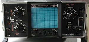
THE OSCILLOSCOPE |
|
|
|
Whilst any scope is better than none, I have yet to see a modern cheap ‘scope the would not perform well with basic microprocessor project use. However, if the choice and the money is there, I would definitely opt for a double beam variant, before paying more for a wider bandwidth. Whilst some might be tempted to make their own - been there, done that - I would really not advise the effort. Whilst it IS possible to produce a working usable piece of test gear, it is unlikely to have a wide enough bandwidth to be seriously useful for microprocessor work. I’ve built FOUR ‘scopes in my time before buying my current model, all of which suffered from this problem. However, I do still have the second venture (in one of my lofts), which was loosely based on a Mullard Students Oscilloscope with er.. VALVES (tubes - to you US folks). With a bandwidth of about 15KHz it was not that useful at diagnosing problems unless they clocked at a relatively low frequency. |
|
|
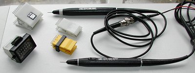
THE MULTIMETER |
|
|
|
Whilst an oscilloscope can perform many of the multimeter’s functions, the meter will give more accurate voltage measurements when setting up and checking +5V power supplies for instance. Also useful for checking the power consumption of projects and when set to the Ohms range, is invaluable for continuity checks when debugging / checking wiring. Can be useful when used in conjunction with a logic probe in a ‘scopeless’ environment to test for ‘floating’ (bad) logic levels. I have both analogue and digital types, even though the digital has an analogue scale. However, as cheap digital types are available for almost nothing these days, there is little excuse not to make this purchase a priority. |
|
|
|
|
|