Micro Projects Home Page

Home

 Microprocessor Basics

Micro Basics

Site Projects

Site Projects

Construction Techniques

Construction

Programming concepts

Software

Projects

Projects

8085 page

8085 page

Fault Finding

Fault Finding

Data Sheets

Data Sheets

EEprom Programmer

Programmer

Video Information

VIDEO info

Peripheral Circuitry

Peripheral circuitry

 Izabella's Programming Class
Picture

CLICK HERE FOR  SIMPLE SOFTWARE ROUTINE WRITING BASICS

Hi there!  As I�m sure you�ll appreciate, we have some members of the class who are already proficient at computer programming of some sort, whilst others may not really have much idea of what is involved. In order to help everyone reach the same level of understanding, I�ll very quickly run through the basics of  what you need to know.  It may be helpful to look at my microprocessor  hardware overview if you haven�t already done so. This will explain where registers and addresses fit in!

To make ANY microprocessor based device work, it needs to be given a properly written program. This program can be written in a high level program like �C� or �Visual Basic�, or a lower level program like �assembler�. Whilst the vast majority of constructors will probably wish to opt for using an �assembler� to compile their code, I�m going to advocate that everyone at least tries their hand at the lowest language of them all, namely, MACHINE CODE. Although more complex than the higher level languages, MACHINE CODE is perfectly straight forward if you take a logical approach to it�s compilation, and by using it, you will need nothing more than the OP CODE listing  to create a working program for almost any microprocessor!

What is a bit of a nuisance is that each different microprocessor uses a different set of  OP CODES with which you write your program. There are however a few cases where they are similar, such as in the case of the Intel x86 and Motorola 68xxx processors, which need to keep some measure of compatibility between new and old architectures.

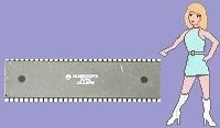
Motorola 68000: 4EF8xxxxh

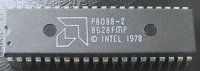
Intel 8088 (x86): E9xxxxh

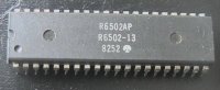
6502 (as in BBC B): 4Cxxxxh

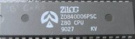
Zilog Z80 series: C3xxxxh

FOOD FOR THOUGHT?

The instructions shown to the left are examples of  almost identical  OP CODES which all do essentially the same thing - ie they cause the program to jump to the memory address shown by the value �xxxx� (also to be written in Hexidecimal). Bear in mind that for most 8 bit processors (something you�ll hopefully settle for initially!) each successive BYTE of the OP CODE instruction will be found in the program at the next consecutive ADDRESS. i.e. in the case of our  6502, the order would  be:

Program counter address

4C


Program counter address +1

34

Jump to location 1234hex

Program counter address +2

12

(note reversal of destination address bytes)

If however, one ever feels compelled to use a 16 bit processor for a home project (as I have done on several occasions) one will be subjected to all manner of addressing peculiarities, such as in the above example, if we were to use the MC68000 equivalent code, the 4E would go in the HIGH bit EPROM, the F8 in the LOW bit EPROM, the high order destination address in the HIGH bit EPROM  (not reversed like in the 6502  example above) ,with the lower order destination address in the LOW bit EPROM. Lost?  I�m not surprised!  According to several authorities, OP code tables are not generally supplied for 16 bit processors as it is not a practical proposition to program them. A few do of course (such as myself); and I call it masochistic programming. Come on folks - some get their kicks climbing mountains, etc. etc.

Picture

HINT:- If one needs the additional facilities of 16 bit architecture, an easy way around the �dual EPROM� scenario , might be to use an 8 bit bus variant, such as an Intel 8088 rather than the 8086.

Oh dear! I think I see a few puzzled faces out there! OK so how about a simple example then? Remember that ALL microprocessors execute their program instructions in sequence unless directed to the contrary, and that ALL microprocessors have at least one ACCUMULATOR register where calculations and program data information can be manipulated by the program that follows it.

Here is an extremely simple program example for the Zilog Z80 that WORKS, but see if you can deduce what is wrong with it:


Program counter address

OP code

Mnemonic

Which in English means....

To the left we

0000h

3E

LDA

Load A register with an immediate value

have the address

0001h

05

xx

; in this case it�s 05hex

as an absolute

0002h

3C

INC A

Increment the current value being held in A

value in HEX

0003h

76

HALT

Stop the processing!

So what does this program actually do then?

After being RESET (either by a power on reset circuit or a hardware reset button) the Z80 defaults straight to memory location 0000h and simply LOADS an IMMEDIATE value (in this case an 05h) into the A register (the ACCUMULATOR). The next instruction INC A  increments the contents of the register by one, (05h + 1h = 06h... easy stuff this!) and the last instruction halts the process completely.. So what�s wrong with it then if it really works?

ANS. In this simple example, we have no way of physically seeing what the calculated answer was!

Central Heating and Z280's

Z280 and  Central Heating  Controllers

Concluding Ideas

Concluding ideas

Links

Links

INITIALISATION ROUTINES

(or in English - what you need to start your programs off with to make them work!)

Picture

OK. So this is where it all starts to come together. The question that seems to come up repeatedly is just what routines are required to start the program off on the right foot? Unfortunately, the answer is not as clear cut as one would like it to be. There are of course values that have to be set up from the software�s point of view, as well as startup codes for hardware devices such as LCD drivers, async and parallel ports. As far as the processor  is concerned, it will need to know the location of it�s system STACK (it�s personally organised temporary storage area), and the location of any interrupt vectors that are to be used. Of course the easiest way to start off programming is simply not to use any of these if at all possible!!

Luckily there are some micro�s that don�t need any routines at all (if you don�t use certain instructions) which make them an absolute doddle to write programs for. Notwithstanding, there�ll be relatively few occasions when one will be prepared to sacrifice processor calls in return for a small amount of software / hardware simplification ( the STACK is a fundamental part of �calls and returns�) so the single initialise instruction will probably cause no hardship...

One of THE most important questions of them all from the home constructor�s  point of view is just how does the Microprocessor behave after a hard RESET? We need to know EXACTLY how it behaves so we can arrange our hardware design accordingly. Whilst some processors start executing their instructions from address 0000h, 0001h, 0002h etc. there are far more that make an immediate jump to another location, (such as FFFF0h in the case of the Intel x86 series) where an instruction MUST reside, telling it just where the main program lies. Without this information, the processor will naturally take the hump...

As this information is SO important to the working of any project, I�ve listed a few types here, each with an example of a suitable initialisation routine.

Picture

Z80 / Z80A-B-C    (84C00)

Unquestionably the easiest processor to use by a long chalk. Introduced in the late 1970�s, the Zilog Z80 was still very much in use (even in it�s original 8 bit form) some 23 years later.

0000h    31

0001h    FF

0002h    F0

0003h........   

And that�s it! Z80 starts off at address 0000h after a reset and we only have to tell it where the STACK space is; in this case at F0FFh as we�ve located our RAM (hardware wise) at the top of the 64K 16bit memory area. Start your program off from location 0003h!

Picture

 8088 (8086 / 80186 / 286 / 386 etc.)

The Intel classic as used in the original PC XT. This processor has 16 bit internals but an external 8 bit bus, which means that (from the home-programmers point of view) there is only one EPROM to program instead of two.

FFFF0    EA FFFF1    00 FFFF2    E0 FFFF3    00 FFFF4    F0

FE000.......   

Considerably more complex than the 8 bit processors, a  number of system and memory variables need to be set up for each different circuit arrangement. The instructions I�ve given here assume for a single  8K EPROM addressed at the top of the IMbyte addressable memory. EAh is a direct intersegment jump, E000h is the relative addressing offset and F000h chooses  the segment. The processor will jump to FE000h absolute - which will be 0000h in the EPROM!

Picture

ROCKWELL / MOS  6502

As used in the well known Acorn and Commodore computers, the 6502 (and it�s variants) are now showing their age. Low cost, wide availability and  programming ease still make it an experimenter�s favourite.

FFFC    00

FFFD    E0

FFFE    00

FFFF    FA


EA00    A2

EA01    FF

EA02    9A

EA03........

Unlike the Z80, the 6502 program EPROM must be situated up at the top of the 64K memory block so that these addresses can be read from startup. FFFC/D point to the program�s start point, whilst FFFE/F address  the interrupt vector- if to be used (In this instance set to FA00h) The STACK location is far less flexible than that used on the Z80 as it must be placed in the bottom �Page 1� area of the RAM. The command in EA00/1 loads a hex FF into the X register, and the 9Ah instruction loads this into the STACK register. STACK is now set down from 1FFFh.

Start your programming from EA03!

Picture

MOTOROLA 68000

My favourite 16 / 32 bit processor. Though every bit as powerful and flexible as the Intel x86 series- the MC68000 makes things a lot easier right from the start by setting it�s initial program counter address at 000000h! Though there are unlikely to be many folks who will brave the machine code world of dual EPROMS, I�m going to list the first few initialising bytes from one of my own  MC68000 programs:

op hi

address Eprom Hi

op lo

address Eprom Lo


00

00000

00

00001

Reset supervisor stack to

17

00002

80

00003

1780

00

00004

00

00005

Reset program counter to

04

00006

00

00007

0400


4E

0064

F8

0065

Interrupt autovector Lev 0

10

0066

00

0067

(in RAM)

4E

0068

F8

0069

Interrupt autovector Lev 1

10

006A

04

006B

(in RAM)


006C


006D

Interrupt autovector Lev 2


006E


006F


Supervisor Mode

30

0400

38

0401

Load D0 with 16 bit 0420

04

0402

20

0403


31

0404

C0

0405

Put D0 value in 1000

10

0406

00

0407


31

0408

C0

0409

Also put in 1004

10

040A

04

040B


30

040C

38

040D

Load D0 with 16 bit 0422

04

040E

22

040F


31

0410

C0

0411

Put D0 value in 1002

10

0412

02

0413


30

0414

38

0415

Load D0 with 16 bit 0424

04

0416

24

0417


31

0418

C0

0419

Put D0 value in 1006

10

041A

06

041B


4E

041C

F8

041D

Jump to 16 bit value 0476

04

041E

76

041F


4E

00420

F8

00421

Initial interrupt vectors

05

00422

18

00423

to be stored in RAM

0C

00424

1A

00425


(last part of supervisor from 041F)

30

0476

7C

0477


17

0478

C0

0479

Move 16 bit addr into A0

4E

047A

60

047B

Put addr A0 in user stack

46

047C

FC

047D

Put immediate in status reg

00

047E

00

047F

(usr mode, interrupt L0)

.....

0480

.....

0481

Your program!

HARDWARE / SOFTWARE NOTES

EPROMS:    0000-07FFh  RAMS:         1000-17FFh

System stack:     1780h     User stack:       17C0h     

68000 BOOT INIT PROC:

Set Supervisor mode       Reset supervisor stack value Reset program counter value Load int vectors into RAM Create User Stack

Set interrupts to level 0

JUMP TO USER MODE

Run user program....

Picture
Picture

And that is the end of my brief lesson on Microprocessor programming. Of course there is insufficient info. here for you to start immediately on that project, (unless you are very clever that is!), so have a look now at the elementary HARDWARE lesson which will explain a bit about the wires and chips side of things if you haven�t already done so. After this,  perhaps it will be a good time to read through our very own constructional site project - the simple Z80 microprocessor based digital clock. Yes I know that we all have digital clocks already, but it will take precious little programming expertise to add functions and facilities that are just not available in off-the-shelf models - or alternatively - remove and set aside the clock EPROM once you�re happy that the circuit works properly and write a completely different application for the clock hardware. Your imagination will be the only limiting factor. Have fun!

BECAUSE OF REPEATED REQUESTS PLEASE CLICK HERE FOR A PAGE ON WRITING SIMPLE SOFTWARE ROUTINES

http://www.hampshire-shops.co.uk