Micro Projects Home Page

Home

 Microprocessor Basics

Micro Basics

Site Projects

Site Projects

Construction Techniques

Construction

Programming concepts

Software

Projects

Projects

8085 page

8085 page

Fault Finding

Fault Finding

Data Sheets

Data Sheets

EEprom Programmer

Programmer

Video Information

VIDEO info

Peripheral Circuitry

Peripheral circuitry

Central Heating and Z280's

Z280 and  Central Heating  Controllers

 Video Basics
Izabella commands attention...


First and foremost, one must remember that the finer details of video vary from country to country, so I will not go into great timing detail. Likewise, as colour complicates the issue somewhat, I will simply describe an example of a simple monochrome video signal.


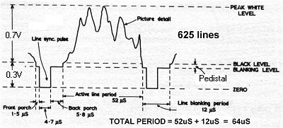
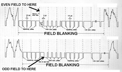
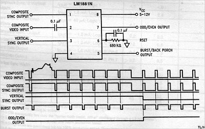
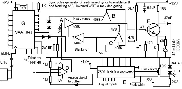
A video signal consists of a reference signal level we shall call ground, with synchronising pulses 0.3Volts below this level and a varying picture information signal up to a maximum of 0.6Volts above this level. (These voltages assume a correctly terminated signal - usually 75 ohms.) Obviously all of these events have to appear at the right time in order to be successfully matchedto a composite monitor (display).

Now there are many ways of creating all those pulses in the right order, but in order to make things a little easier for oneself (especially if one has the job of creating a digital picture interface) I would strongly recommend using an SPG chip to do this part. SPG? Sync pulse generator. This IC, when given a suitable clock input, and genlock phase locked loop (PLL) if desired, will give the correct sequence of pulses for the TV standard required. It will still be necessary to make a proper interface however, to mate the SPG to the actual monitor itself.

As far as the digital interface is concerned, it will be necessary to investigate the chosen SPG chip to see what output signals are available for the micro (hopefully at TTL level) By using these signals, it will then be possible to work out the times during the video signal itself when one can download information into the Video RAM being used for the display without interfering with the actual picture whilst its being displayed.

The circuitry examples given here are extremely simple, but have been tried and tested and worked extremely well in the receiver of my Video Transmission Unit. Of course, the resolution is pretty poor - as to be expected with the amount of RAM being used (about 11K for the whole picture) - but there is nothing to stop anyone adding more RAM and using a much faster processor to achieve a far more detailed picture. As you can see, the actual video generatingbit of circuitry is totally free-running and does not need to use the processor to give a picture. As soon as the processor comes on-lineso to speak, IT has to synchronise its data transfer to coincide with blank portions of the display.

VIDEO THEORY

So where do we start? Many books have been written on the subject so Ill gloss over a great deal by necessity. To the right we see a typical monochrome 625 line video waveform. The voltage from peak white to the bottom of the sync pulses is typically 1Volt into 75ohms.

Video waveform

The sync pulses are to synchronise the receiver to the video signal with a front porch and back porch to either side. This gives 12uS of blanking, i.e. a time when no video signal is present. The video signal itself is 52uS. Where a simple RAM is used as an interface between a micro and the video, the only time the micro can access the RAM is when the video is not using it, i.e. in the blanking time. If one bears in mind that an ordinary 8 bit processor like a Z80 running at 4MHz takes 4x clock cycles to complete the shortest instruction (i.e. 1uS) then you can see that there is very little time to do much data transfer between the processor and the RAM before the next active line period comes along.

Field blanking

With an interlaced picture, there is an odd and an even field. See the picture to the left and note the small differences between the two. The field blanking is fortunately long enough to do a lot of RAM refreshing behind the scenes. With a 625 line video signal, this blanking is typically 20 lines long- i.e. 1.28mS. Of course one could conceivably loosea line or two at the extreme top or the bottom of the raster to gain a few extra micro seconds grace..

Whilst not essential to any video grabbing project, the SYNC STRIPPER like the LM1881 shown to the right saves a lot of circuitry. Look at the waveforms it generates in the table. I used this IC in my video transmission project. The vertical sync was used to inform the micro that the next new field is on its way. Remember that as the micro is so slow, relatively, that any triggers such as these have to act well in advance of the event to give it time to prepare for data transfer etc. The composite sync output I used to synchronise and gate the digital pixel clock

LM1881 sync stripper
Concluding Ideas

Concluding ideas

An important point to note about pixel clocks etc. is that synchronisation here is of paramount importance as the edge of the picture will either appear jagged or will ripple up and down over time. All very unsatisfactory! Hence one generally chooses a very high frequency pixel clock so that when it is gated, the smallest time differences occur. My original circuit started off life with a 12MHz pixel clock, but was soon upgraded to a 50MHz one (then divided down of course) which gave a perfectly cleanedge to the picture.

Links

Links

SIMPLE VIDEO GENERATOR

scrappy video generator schematic

The rather sketchy diagram above shows an interface of mine for a programmable cross hatch generator circuit that can display anything from a simple cross-cross hatch to a test card style image complete with 256 grey scale photo- image in the centre!

The SAA1043 sync pulse generator (G)is fed with a 5MHz clock. Appropriate video signals are generated and drive the enables of analog transmission gates B & C. When these are enabled, the conditions at the input of transistor (F) are altered to generate sync pulses and picture information at its output.Digital to analog converter (E) has its references set by the black level pot and the voltage drop across the LED and diode going into pins 1 and 2/3 respectively. When the D-A is synchronised to read from memory, it will output a signal at the appropriate level, which is the buffered by op amp (D) and fed into the transistor via transmission gate (A). Its a very crude sort of circuit but it works exceedingly well once set up correctly. Note that when set up for a simple cross hatch, all the inputs to the A-D are held low and the hatch information is injected into the MSB pin (D7).

Marconi No. 1 Chart

The Marconi No1 resolution chart is used to check for a correctly set up system. The castellations at the edges show the extremities of the picture (only seen with an underscanned monitor) with the lines (or hatching) showing correct linearity and picture shape. The circles confirm this and prove the system both in the centre and the corners of the picture. The numbers on the gratings show the systems equivalent horizontal resolution; the edges generally being significantly worse than the centre. Note the moire patterning within some of these caused by the grating beatingwith the resolution of the scanner and the resizing of the image. It is certainly interesting to relate the difference between the resolution of a standard VHS recorder at approx 240-250 lines and compare it to SVHS at 400 lines. Likewise the resolution drop of using a composite signal connection for that Svideo source which will reduce it to nearer 350 lines.

Perhaps now is the time to show some examples of what sort of results can be expected from the simplest sort of video capturing project like mine. As Ive stated before, the resolution is very low, but this is of little consequence as the device was meant to be used for surveillance over a large area such as a compound, triggering off its own alarmindication when movement is detected (i.e. the video level changes beyond pre-determined points).

SPECIFICATIONS

The following figures might be of interest when considering the quality of the images delivered. Just over 11K of RAM is needed to store 1x complete picture image. Resolution is 161 pixels wide by 69 deep. Grey scale has a maximum of 64 steps. Communications was expected to be a very slow and unreliable connection of 1200 baud - i.e a new data word every 6.6mS approx.

Garbage in video RAM on reset

When powering up the receiving end, if the processor is held in reset, the contents of the RAM is literally garbage as can be seen in the picture to the left. In this image it is quite easy to see how large the pixels are.

Revelation and a semblance of order is seen at last to the right! On releasing the reset button of the processor, the RAM is rapidly cleared from top to bottom and two grey scales are set up on the screen for adjusting the monitor. The top one is actually quite artificial, in as much as the system can only ever transfer images containing a maximum of 64 grey scale steps... The lower ramp is of course only 16 steps.

256 and 16 level grey scales
transmitted chart pik

Ow! Now that is painful to look at isnt it? Mind you, in all fairness, Ive seen video camera systems apparently giving a very clean and acceptable picture look positively dreadful when confronted with a resolution chart.The purpose behind using the chart in a case like my system is to prove that i) The picture is all there. ii) The circles are all round iii) Linearity is correct. iv) The edges of the vertical lines are comparativley straight.

And a real picture to the right? Once again poor, but in practice the project worked extremely well at identifying movement in a compound; namely the job it was intended to do. The circuit as it stands would be clearly capable of a vastly superior performance were there at least twice as many pixels in both the horizontal and vertical planes, with a minimum of 256 grey scale steps. Food for thought?

A photograph as received

A few more technical odds and ends for those who are interested...

The microprocessor used in both the transmitter and receiver were Z80As running at 4MHz. Comms was achieved by using Z80 SIO/2s. RAMs were standard 55257 32K devices. One needed at least twice the maximum picture size for the RAM as the data was doubled upto make a comparison between the last picture seen and the new one, to make meaningful comparisons for movement detection purposes. Video RAM busses were multiplexed with both LS244s and HC244s.

VIDEO INPUT

Video signal enters the transmitter board splits, and drives the LM1881 sync stripper and a TDK2485 device that splits the Chroma (colour) picture information away from the Luminance (intensity) information. (In my project, the Chroma is discarded as we are only interested in a monochrome signal.) The Luma is then buffered and fed into a 6 bit CA3300 flash A-D converter. This is then interfaced to the micros bus via an HC244 octal buffer. This information is continually clocked into the RAM by the aid of some HC4040 counter ICs. The Z80 has to take its time in compiling this information during the blanking periods. A 7529 D-A converter was included in the circuit for diagnostic purposes to check for correct black and white clip levels etc.

VIDEO OUTPUT

The free-running video generation circuit is virtually identical to that shown for the cross-hatch generator shown further up the page. An SAA1043 tuned to the correct frequency by a varicap diode provides the syncs, with a ZTX109 doing the video mixing. An OP16 is used as the video buffer with a couple of ICL7660s providing the negative voltages. Once again, HC4040s are used for the free running clock to extract the video information from the RAM and send it to the D-A. Several delay circuits are used in the project, all of which are 555 timers that have proved to be amply stable for this purpose. Apologies that I no longer hold the full schematics for this project. All I have is the development material and the prototypes.

http://www.hampshire-shops.co.uk