Cable Tester
Micro Projects Home Page

Home

 Microprocessor Basics

Micro Basics

Site Projects

Site Projects

Construction Techniques

Construction

Programming concepts

Software

Projects

Projects

8085 page

8085 page

Fault Finding

Fault Finding

Data Sheets

Data Sheets

EEprom Programmer

Programmer

Video Information

VIDEO info

Peripheral Circuitry

Peripheral circuitry

Central Heating and Z280's

Z280 and  Central Heating  Controllers

Concluding Ideas
Picture

The simple example on the left was to show the concept to be used. Knocked up over the weekend, it tests an �S� video 4 way minidin cable for shorts, crossovers and open circuit conductors. In addition to the 4 digit display showing the status, two LEDs are used for quick identification of a �Pass / Fail� condition.

The following selection of images show the �finished article� - so to speak.

Picture

To the left we see the finished prototype built on a standard �eurocard� with two DIN 41412 connectors at the top. One is for all the inputs, with the other dedicated to outputs. The 16 character display shows operating menu instructions and other relevant information.

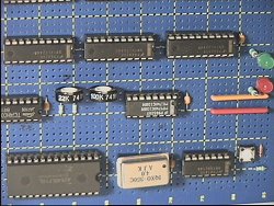
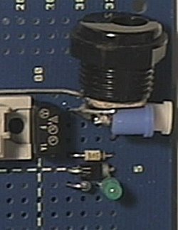
The two pots near to the middle of this image are for the display adjustment, one for the viewing angle, and the other for the �E� timing �pulse stretcher�. The latter is needed as this particular display seems to have been designed for the 63xx / 68xx families of processors.

Picture
Picture

Here we can see a close-up of the display showing an inbuilt diagnostic routine, that checks to see that all the port inputs are working ok. Testing is achieved by taking any line low, with the corresponding number coming up on the display. Can also be useful for testing individual conductors in cable assemblies.

Picture

Simple but essential; the power input to the board. Here we see the power socket with two smaller take-offs. Also note the green power LED, the decoupling capacitor and the diodes for transient / reverse voltage protection.

Click here for a page of notes I made for the original �RAMless� prototype cable tester for the 4 way minidin lead. One simply has to apply the observations to a basic Z80 processor schematic.

Cab test proto notes

SCHEMATIC x 3

Video
Video
Video

Click on these three links to show the �official� circuit diagram for the production model as drawn on �Orcad�. This is the actual circuit as constructed on the blue coloured boards shown above. It may be of interest to know that the EEprom programmer shown elsewhere on this site was used to download the software into the EEprom for this project.

Concluding ideas

Video

Data sheet for the LM020 display used.

Links
Video

Cable tester preliminary software and operating procedures.

Links

http://www.hampshire-shops.co.uk