|
|
 |
|
|
|
TIMEBASE |
Unlike the DIGITAL CLOCK project that uses a 50Hz timebase, the STOPWATCH 3 uses 100Hz so you will therefore almost certainly need to build a crystal oscillator which can be divided down to 100Hz. One may of course use the same oscillator to drive the CPU clock pin! (not at 100Hz though...!) |
RAM |
Whilst the CLOCK needs no RAM to work, the STOPWATCH 3 needs sufficient capacity for the stack, various areas of temporary storage PLUS room to save all the captured finishing times to be recalled at the end of the race. The circuit must therefore have 2K RAM fitted. (Like the 6116 already shown connected in the CLOCK schematic) |
CONTROLS |
STOPWATCH 3 needs a total of SIX buttons to operate correctly. These are interfaced via the same 74LS374 (designated IC4 in the Clock schematic) - but obviously using the first SIX inputs (D0-D5) as opposed to the clock’s FIVE. Input D7 in keeping with the CLOCK needs to be fed from the TIMEBASE output of 100Hz. |
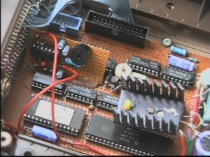
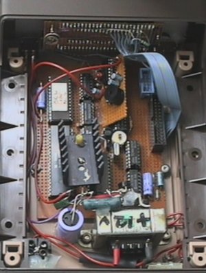
SCHEMATIC |
Use the DIGITAL CLOCK schematic ‘as is’ along with the wiring list. Note that once this has been built, all that will be left to complete will be: A) The crystal timebase and CPU clock oscillator. B) The PSU of your choice. C) The buttons and their simple interface. D) The wiring to the display of your choice. |
DISPLAY |
If using the DL1414 displays, no decoder is needed for the digits. If however the TIL311 or any of the many other displays out there are used, one will probably be required. The SOFTWARE sends each number to each digit in a single 8 bit word. The BOTTOM 4 bits (D0-D3) are the number to be displayed - i.e. 0-9, and bits 4 and 5 are the ADDRESS. Address 0 points to the far right display, address 1 to the second from the right and so on. Look at the example of this sort of decoding on my TIL311 data sheet til311op.jpg. Here you’ll see Data Bus lines D4,5,6 being used in conjunction with an HCT138 for this exact purpose. If you are going to use the DL1414 (two off for the 8 digits) you can refer immediately to the display schematic in my DATA SHEETS heading under DL1414 (naturally!) The circuit you want is the one designated ‘simple hex only wiring’; the image designation being dl1414op.jpg. This was actually taken from the prototype and needs no alteration whatsoever. |
OSCILLATOR |
If using a crystal and a simple divider to 100Hz to supply both the CPU and the TIMEBASE then a readily available 3,276,800Mhz crystal will be ideal. This will divide down to 100Hz without any special divide ratio’s. You can of course opt for separate clocks, with the CPU frequency being your choice and an oscillator with a 32,768KHz watch crystal for the dividers of the timebase. Your decision in the end. Mind you, I did have one young lady who’s on UK 50Hz mains, telling me that she used a simple step-up frequency doubler from her AC coupled Opto- Isolator...50Hz increased x2 to 100Hz? Ingenious but simple! There is a nice stable and reliable crystal oscillator in my ‘Peripheral Circuitry’ corner if you need one.. |
|
|
|